
Every blinking LED, every spinning motor and every sensor reading comes down to a handful of humble parts. You do not need a warehouse to get started. A small box of components, chosen well, will carry you through hundreds of projects, from a flashing night light to a line-following robot. What follows is the set most experienced makers keep within arm's reach, with a note on why each part earns its place and what to look for when you buy.
Breadboard and jumper wires: your workbench
A solderless breadboard is where circuits are born and abandoned. A standard 830-tie-point board gives you two power rails and enough rows for most beginner builds. Inside, the holes are joined in strips: the five holes in column A through E are connected, the same goes for F through J, and the centre channel separates the two halves so a DIP chip can straddle it. The power rails run the length of the board, and on many cheap boards they split in the middle — check with a multimeter in continuity mode if a circuit behaves oddly.
Buy a pack of pre-cut jumper wires in three types: male-to-male for board-to-board, male-to-female for sensors, and a few female-to-female. Solid-core 22 AWG wire and a pair of wire strippers are handy for custom lengths. Adopt a colour habit early: red for positive, black for ground, everything else for signals. Future you will thank present you when debugging a tangle of twenty wires.
Resistors: small, cheap, and non-negotiable
Resistors limit current, divide voltage and hold a pin at a known level. Skipping one is the fastest way to kill an LED or a microcontroller pin. You will read values from the colour bands or, more reliably, with a multimeter on the resistance setting. A few values cover most beginner work:
- 220 Ω and 330 Ω — current limiting for LEDs on 3.3 V and 5 V supplies.
- 1 kΩ — transistor base resistors, simple voltage dividers.
- 10 kΩ — pull-up and pull-down resistors for buttons and sensors, the most-used value in any drawer.
- 100 kΩ — timing networks, sensor dividers, discharging capacitors.
An E12 assortment from 1 Ω to 1 MΩ, ten of each, costs very little and lasts years. Quarter-watt, five-percent tolerance parts are fine for learning. If you need a value you do not have, two resistors in series add up, and two equal resistors in parallel halve.
LEDs and diodes
Light-emitting diodes show you that a circuit is alive. Red, yellow and green types drop roughly 1.8 to 2.2 V; blue and white ones need around 3 V, so they behave badly on a 3.3 V supply without care. Aim for 10 to 20 mA. On a 5 V supply with a red LED, (5 − 2) ÷ 0.015 gives about 200 Ω, so a 220 Ω resistor is the sensible pick.
LEDs are polarised. The longer leg and the rounded side of the plastic are the anode, which goes toward the positive supply. Ordinary diodes matter too: a 1N4148 for signal work, a 1N4007 for rectifying and for clamping the voltage spike a motor or relay coil produces when it switches off. Use a diode across any coil you drive, with the stripe facing the positive rail.
Capacitors: short-term energy storage
Capacitors smooth shaky supplies, set timing, and block DC while passing AC. Two families cover the beginner toolkit, and mixing them up causes real confusion.
Ceramic (non-polarised)
Small values from a few picofarads to about 1 µF. A 100 nF ceramic placed close to a chip's power pins is standard practice and solves a surprising number of mysterious resets. They can go in either way round.
Electrolytic (polarised)
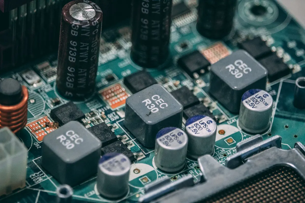
Values from 1 µF up to thousands. The stripe with minus signs marks the negative leg, which goes to ground. Reversing one can make it vent, so check twice before powering up. Keep the working voltage rating comfortably above your supply: 16 V or 25 V parts suit 5 V and 12 V projects. A mix of 10 µF, 100 µF and 470 µF handles most smoothing jobs.
Transistors, switches and buttons
A microcontroller pin can only supply a few tens of milliamps, nowhere near enough for a motor or a relay. An NPN transistor such as a BC547 or 2N2222 acts as a switch: emitter to ground, collector to the load's negative side, load's positive side to the supply, and a 1 kΩ resistor from the base to your control pin. Add a flyback diode if the load is a coil.
Tactile push buttons are the simplest input you can wire. Remember that a floating input pin reads noise, so pair every button with a 10 kΩ pull-up or pull-down resistor, or enable the internal pull-up if your board has one. Switches, toggle and slide types, are useful for cutting power to a whole project.
Potentiometers, sensors and a few useful ICs
A 10 kΩ potentiometer has three legs and works as an adjustable voltage divider, perfect for dimming an LED or setting a threshold. Beyond that, a starter sensor set gives your projects something to react to: a light-dependent resistor, a thermistor, a push-button module, an ultrasonic distance sensor and a passive infrared motion sensor. Each one talks to a microcontroller with a couple of wires.
Four integrated circuits earn their space early:
- 555 timer — flashing, beeping and timing without any code.
- LM358 op-amp — comparing and amplifying small signals.
- 7805 regulator — turning 9 V or 12 V into a steady 5 V.
- 74HC595 shift register — driving eight outputs from three pins.
Power and measurement
Nothing runs without power, and nothing gets fixed without a way to measure. Keep a battery holder with a switch, a 9 V snap connector with a barrel jack, and a USB-to-5 V breakout board so you can run projects from a phone charger or power bank. Whenever two boards share a circuit, join their ground pins first; most "it does not work" problems are a missing common ground.
A basic digital multimeter is the single most useful tool in the box. Learn three modes: continuity for checking connections, DC volts for confirming a supply, and resistance for identifying unmarked parts. Measuring current means placing the meter in series with the circuit, not across it, and most meters have a separate socket for that. Set the dial before you connect the probes.
Building the kit without overspending
Start small and add as projects demand. A sensible order looks like this:
- Buy a breadboard, a jumper wire set and a resistor assortment.
- Add LEDs and a bag of 220 Ω resistors, then build a simple light.
- Add capacitors, transistors and a few diodes.
- Add a multimeter before your second or third project, not after a failure.
- Add sensors and ICs once you can wire a button and an LED reliably.
Buy resistors, capacitors and LEDs in packs of ten or more, since losing one is easier than finding it. Sort components into labelled baggies or a resistor organiser, and write the value on the label rather than trusting memory. When something does not work, check power, check ground, then check polarity — in that order. Most circuits fail for one of those three reasons, and a tidy toolkit makes all of them quick to rule out.
Photo: Muffin Creatives / Pexels